Supported architecture
The intended power path is battery → protection/disconnect hardware → electronic speed controller (ESC) → brushless thruster. A regulated low-voltage branch supplies the Raspberry Pi Pico controller and sensing. The intended command path is wrist input → controller → ESC pulse-width-modulation command. Emergency switching and pressure, temperature, current and moisture monitoring are intended protective interfaces. Their integration and fault response have not been demonstrated in the supplied record. Electrical design sources, T04
For the product concept, the propulsion/mounting subsystem carries two thigh thrusters and straps/buckles; the separate battery enclosure is intended at the side of the tank; the wrist interface provides on-demand control. The functional prototype scope and stand-ins are governed by D04. Cable estimates describe proposed routes, not an as-built harness. A07
Component and interface record
| Subsystem | Latest supported description | Evidence boundary |
|---|---|---|
| Propulsion | APISQUEEN + ESC appears in SD2 procurement; GA3 bench photo shows a blue/red thruster and an APISQUEEN ESC labeled 100 A | Exact thruster and ESC variants/settings unconfirmed; the ESC label is not measured system current or continuous capability |
| Battery | GA3 photographed label states 24 V lithium-ion, 6000 mAh, charge current 1–3 A and charging voltage 29.4 VDC | Label specifications only; brand/model, protection and measured capacity unconfirmed. These are not charging instructions |
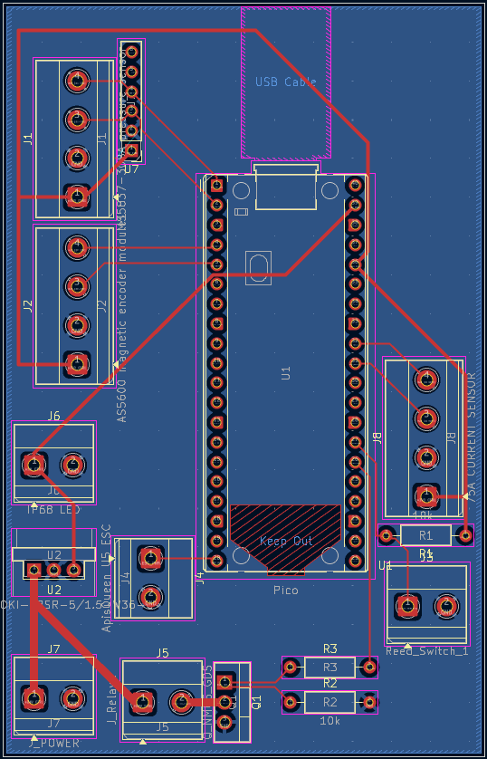
| Power regulation/control | Pico RP2040, a buck converter, relay/switching and throttle interfaces appear in the design/order records | As-built populated circuit and authoritative PCB revision not established |
| Wrist interface | Magnetic encoder/input and switch mechanism in a threaded printed housing | Printed fit problems documented in T02; complete underwater throttle/stop use unverified |
| Sensing | AS5600 magnetic encoder and TMP117 temperature sensing proposed; current, pressure and moisture monitoring also planned | Orders change current sensor from a TLE4971-related 75 A selection to ACS725LLCTR-50AB-T; pressure replacement listed as 114991178. Ordering does not establish integration or calibration |
| PCB | GA3 presents a space-optimized PCB layout; narrative holds manufacturing pending physical circuit testing | “Completed prototype” wording refers to design progress, not proof of a manufactured, populated and tested board |
| Propulsion mounting | Thigh-mount CAD and printed mount iterations; straps, fasteners, washers and buckles planned for assembly | Printed thruster forms include stand-ins; complete operational wearable assembly and retention loads unverified |
| Battery enclosure | Threaded cap/sleeve, tube, O-ring and cable-entry concepts | Final assembled revision and pressure qualification absent |
V1 circuit descriptions use a 22.2 V battery, a 40 A fuse, disconnect/
Enclosure geometry and material status
GA3 labels the cap and sleeve PLA, with 2 in thread depth, a “3.2500-4” designation and 0.25 in pitch override. It lists cap diameter 3.15 in and sleeve diameter 3.154 in. These are source CAD annotations, not inspected native dimensions, production tolerances or proof of a seal. The same presentation identifies an EPDM AS568-233 O-ring, 2.859 in inside diameter, 3.137 in outside diameter and 0.139 in width. Later/repeated order entries specify AS568-232 and link Buna-N, so the actual fitted seal cannot be selected from the presentation alone. GA3, procurement
Tube descriptions also conflict: the September 29 enclosure narrative says polyvinyl chloride (PVC); an order says clear acrylic while linked item text says polycarbonate. PETG coupon notes do not establish the cap/sleeve material or coating. The architecture is therefore a supported concept with uncertain as-built material/seal identity. Enclosure check-in, coupon notes